Exposure Time and Motion Blur: How to Calculate and Verify Strobe Timing on a Moving Line
Motion blur is one of the most common reasons an inspection that works with a stationary sample fails at production speed. The cause is simple: the part moves while the sensor is collecting light. The fix is less simple, because shortening exposure needs more light, and more light usually means a strobe whose timing must line up with the camera. Deyi Vision, a machine vision supplier based in Foshan, China, covers both halves of the problem in two engineering notes. This article combines them into one workflow.
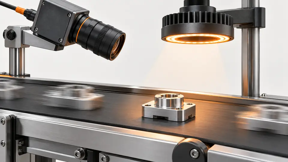
Engineering illustration of how exposure time and conveyor speed produce motion blur in pixels. Image: deyivision.com.
Step one: express blur in pixels
Deyi Vision's note on exposure time and motion blur calculation starts by converting everything into the same unit. Motion blur in object space is speed multiplied by exposure time. To know whether it matters, divide that distance by the object-space size of one pixel.
The note uses a hypothetical example. A 100 mm field of view imaged across 2000 pixels gives 0.05 mm per pixel. If the part moves at 500 mm/s and the application can tolerate 0.5 pixel of blur, the allowed blur is 0.025 mm, so the exposure ceiling is 0.025 mm divided by 500 mm/s, or 50 µs. These figures illustrate the arithmetic only; your own blur budget depends on the feature size and the measurement or detection task.
Why the blur budget matters
Detection tasks such as presence checks can usually tolerate more blur than gauging tasks, where a smeared edge directly shifts the measured position. Decide the blur budget from the smallest feature or tolerance you need to resolve, not from a general rule.
Step two: find enough light for the short exposure
A 50 µs exposure collects far less light than a 5 ms one. Raising gain to compensate adds noise, and opening the aperture costs depth of field. Most fast lines therefore use pulsed or overdriven lighting, matched to the camera exposure. Lighting choice belongs in the same review: Deyi Vision's machine vision lighting range and its guide on how to choose machine vision lighting treat brightness, geometry and pulse capability together rather than separately. It also helps to remember that the light budget depends on the whole optical path: lens aperture, working distance, part reflectance and any filters all change how much of the strobe energy reaches the sensor. A bench test with the real part and the real lens at the planned exposure is the quickest way to find out whether the design has enough margin.
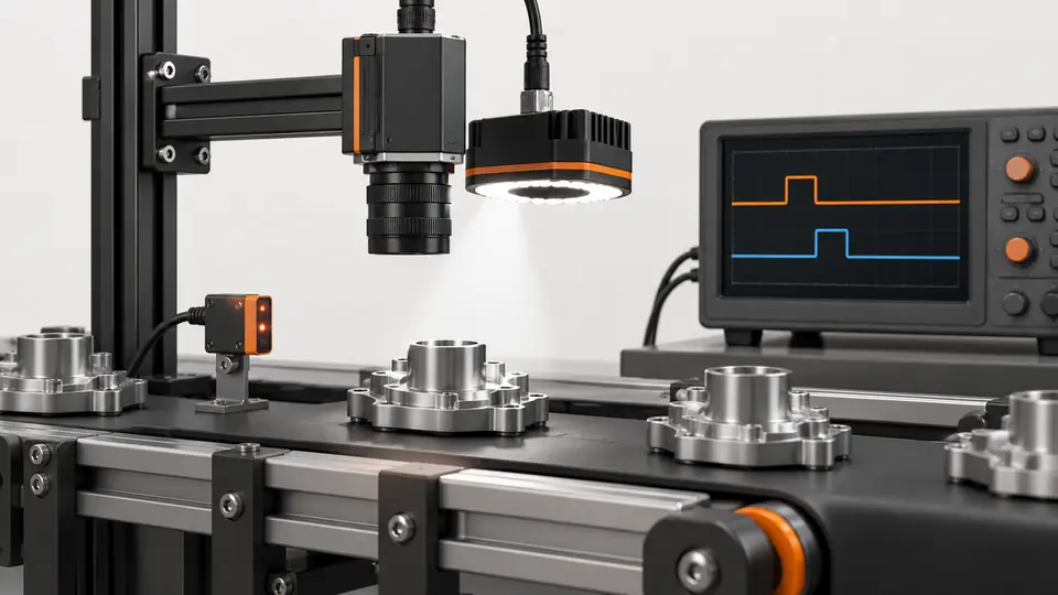
Engineering illustration of strobe pulse timing overlapping a camera exposure window. Image: deyivision.com.
Step three: verify that strobe and exposure actually overlap
The second note, on strobe and exposure timing verification, deals with a failure that is easy to miss. A strobe that fires slightly early or late, or a pulse shorter than the exposure, can produce images that are darker, unevenly lit or blurred in ways that look like an optics problem. The note's advice is to measure rather than assume: observe the trigger, exposure-active and strobe signals together, check the delay and duration of each, and confirm the overlap at the actual production trigger rate.
Points to check include:
- The delay between trigger input and exposure start
- Exposure duration compared with strobe pulse duration
- Jitter from part to part, not only a single capture
- Whether the timing still holds at the highest trigger rate the line will see
Record the settings that were verified
Once timing is confirmed, freeze and document the camera, strobe and trigger settings. A later change to exposure or to the trigger source should trigger a repeat of the timing check, not just a visual glance at a few images.
Line-scan cameras add encoder timing
With line-scan cameras the image is built line by line as the part moves, so the line trigger must follow the motion. Deyi Vision's line scan camera with encoder guide explains why encoder-triggered acquisition keeps pixel aspect ratio stable when speed changes, while a free-running line rate stretches or compresses the image. Exposure per line must still fit inside the line period, and the lighting must be bright enough for that short window.
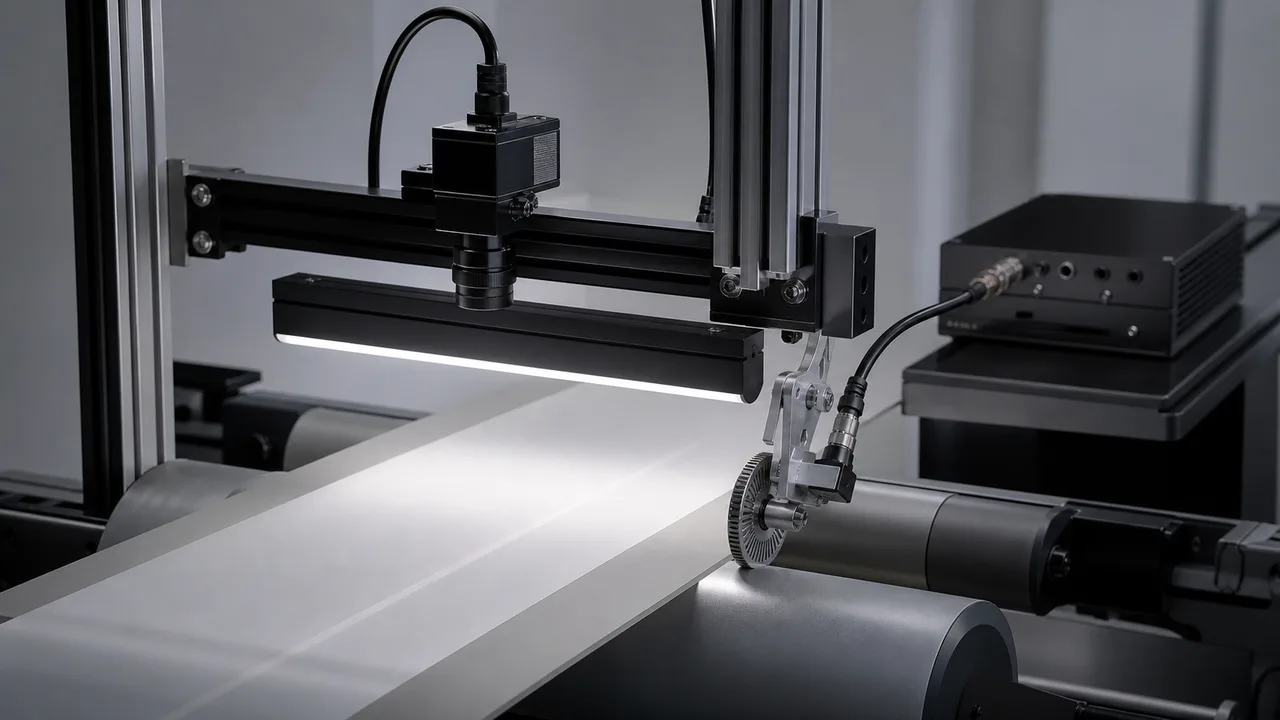
Line scan camera inspection setup with encoder-synchronised web motion. Image: deyivision.com.
Putting it into a project specification
For an RFQ or acceptance test, write down the field of view, pixel count, maximum part speed, allowed blur in pixels, the resulting exposure ceiling, the lighting mode and the trigger source. Then specify how strobe overlap will be measured and at which trigger rate. Deyi Vision's industrial 2D cameras and line-scan cameras can be reviewed against those numbers, and engineering questions can be sent through the contact page with sample images and line data.
FAQ
How do I calculate the maximum exposure time for a moving part?
Divide the allowed blur in object space (allowed pixels times mm per pixel) by the part speed. In Deyi Vision's hypothetical example, 0.025 mm at 500 mm/s gives 50 µs.
Why are my images dark or uneven even though exposure is short enough?
The strobe pulse may not fully overlap the exposure window. Measure trigger, exposure and strobe signals together at the real trigger rate.
Can higher gain replace a brighter strobe?
Only partly. Gain amplifies noise along with signal, so very short exposures usually need more light rather than more gain.
What changes for line-scan cameras?
Lines should be triggered from an encoder so that image geometry follows the real motion, and each line's exposure must fit inside the line period.
Contact Deyi Vision: email sales@deyivision.com · deyivision.com